Connection of fans for different voltages.
This text was automatically translated using Google Translate.
Sometimes we get into a situation where we need to connect the fan to a different voltage than the one on which the rest of the printer works. Whether due to the voltage at which our printer runs (eg Ender 3 operates at 24V), the piece we have not produced (typically Noctua (12V) for cooling the V6 hotend ) is not produced, or we have a supply of fans for this voltage in a drawer .
RepRap
The vast majority of motherboards for 3D printers, based on their involvement, more or less, is based on the original open source project RepRap . It's also not much to come up with, at least as far as the connection, switching and control of the fans is concerned.
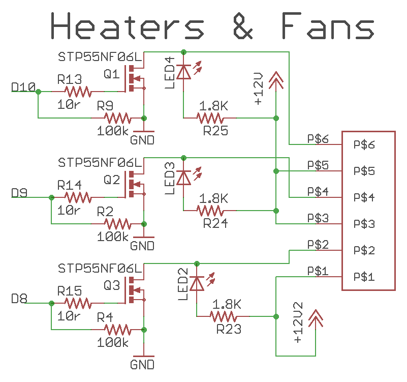 |
As can be seen in the original diagram of the shield module for the Arduino Mega, a MOSFET transistor is connected to one pin of the processor, which switches GND, or ground, against a voltage of 12V. Resp. against any voltage. |
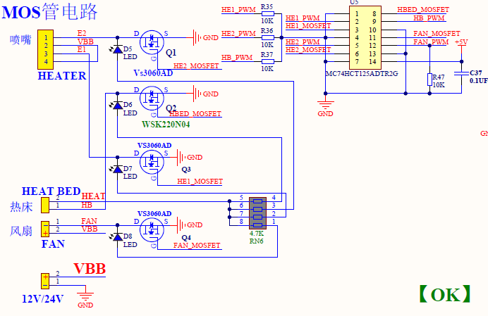 |
In the cut-out of the diagram to the SKR control board, we see that basically nothing has changed, the principle is still the same. |
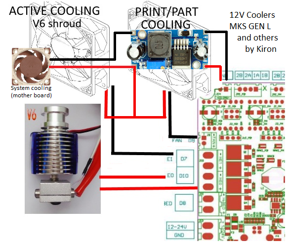
When connecting the fans to a voltage other than that provided by our control board, we will create a branch of the required voltage using a step-down converter. At the input, we connect the step-down converter basically anywhere where we get the source of the original voltage. However, a stable 24V voltage output, which is used to connect the motherboard cooling fans, is best suited for this. In the event of an emergency, we can also use the power supply directly from the source from which our control board is powered.
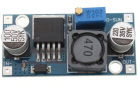 |
We buy a step-down converter anywhere, the dealers with Arduino and all stores with electronic components have them. I used this from AliExpress, I have verified it and it has been working for a long time without the slightest problem and the voltage at its output is stable. |
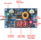 |
Of course, you can also use a more advanced step-down converter with a built-in voltmeter. Any other light on your printer will surely be appreciated by visitors :) |
We connect the inverter to the input voltage, we connect a 24V fan to the output so that the step-down has some load, and we set the output voltage that we require with a trimmer. Typically it is 12V, but it can be 5V. This creates the voltage source in the printer that we require, and we can proceed to connect the fans.
Fan connection
The principle of this solution is that we use ONE step-down converter for all fans at a given voltage.
The principle is simple. The negative poles of the fans (which we want to supply with a different voltage than the original voltage) are normally connected to the control board (as they were originally), but we unplug the positive pole from the connector and connect it to the step-down output of the inverter. Thus, the respective MOSFET will switch the ground against the 12V voltage created by us, and all functions will work for us, incl. independent control of each fan using PWM. I used to draw it semi-pathically like this :)
I remind you that only people who know what they are doing should go into this. That's why I don't give detailed photos or videos of how to involve it here.