How to connect inductive probe P.I.N.D.A. v2
This text was automatically translated using Google Translate.
There are many different ways to deal with ABL, or Automatic Calibration of the print pad. Currently, the two most common are: BL TOUCH and an induction probe. Today we will show how to connect an induction probe on the example of the Ender 3 printer, with motherboards from the MKS and SKR families.
Basic features of the induction probe:
- Accuracy - the probe works with an accuracy of hundreds of mm - here, of course, depends on how high-quality Chinese clone you buy.
- It has no mechanical moving parts - it has nothing to break, fall, wear, etc.
- It reacts only to metal. This is the reason why the capacitive probe, which responds to everything, incl. dust, warm air and print.
- The condition is the use of a steel washer - or equivalent - we wrote about here .
- The probe is connected only instead of Z enstop - there is no need to connect a "servo".
- PINDA v2 has a temperature sensor, the implementation of which is being prepared and tested in Marlin. That is why we are releasing now.
Purchase of a probe
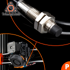 | If you have the opportunity to get the original probe from Průša Research , do not hesitate. However, a clone from the Trianglelab company will serve just as well. Unfortunately, this version probably has the same short cable for use in Ender 3 (as well as Průša). But it's nothing that can't be survived. |
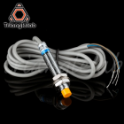 | Trianglelab also produces a version without a temperature sensor, but with a longer cable. However, any connector is missing and soldering will not be avoided anyway. |
Hotend preparation - assembly
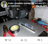
 | As I wrote in the article OctoEnder, or "drilling" the printer , I used the tank type hotend and modified it to attach the induction probe. |
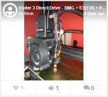
 | A similar adjustment was also made by Jakub Kellner for the bowden solution. |
 | This holder will do the same service for the original hotend. (not tested) |
Of course, you can use any other solution.
Attach the probe so that it is approx. 2 - 3 mm above the level of the nozzle. It is a bit necessary to work with it and I recommend testing on any piece of other metal so that you do not damage your PEI pad.
Cabling connection
This is where the fun begins. The PINDA v2 probe has 4 pins on the output, of which we will use only 3. The original from Průša Reasearch also has a shorter cable than needed for Ender 3. Here I would like to appeal to Chose to remember when designing his printers that his parts will also be used by Enderáci :).
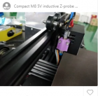
The color coding of the output cables for both of the above probes is as follows (for the version without a temperature sensor, the white cable is missing):
| BLACK | Output signal from the probe |
| BLUE | GND, or ground |
| BROWN (brown) | + 5V |
| WHITE | Temperature sensor output |
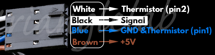
The connection from the endstop on the boards from the MKS and SKR families looks like this:
Therefore, we will either make an extension for a short cable version 2, or we power the connector for version 1 so that we have a + 5V power supply at the top, GND in the middle and an output from the sensor at the bottom, connected to pin 1.25 on the SKR 1.3 board. The temperature sensor then goes to port 0.25 (TH1). The connection on the MKS GEN-L board is the same, only the pin designation is D18 and A15 for the temperature sensor.
We don't have to remember the pin number in the above solution, in Marlin it is remembered for us by #define Z_MIN_PROBE_USES_Z_MIN_ENDSTOP_PIN
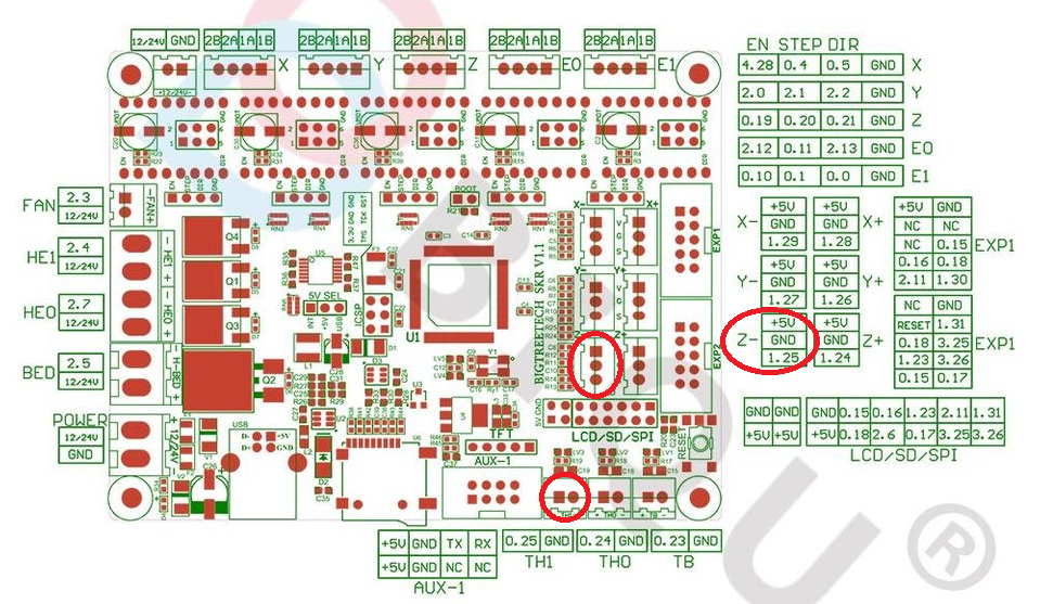
The resulting reduction could look like this:
Setting up in Marlin
#define Z_MIN_PROBE_ENDSTOP_INVERTING false
#define Z_MIN_PROBE_USES_Z_MIN_ENDSTOP_PIN
#define FIX_MOUNTED_PROBE
#define NOZZLE_TO_PROBE_OFFSET {33, 5, 0} - here we set the position of the probe relative to the nozzle.
#define AUTO_BED_LEVELING_BILINEAR

If we have a dual Z installed with two independently controlled motors, we can use a probe to calibrate their relative positions.

#define Z_STEPPER_AUTO_ALIGN
#define Z_STEPPER_ALIGN_XY {{38, 190}, {190, 190}} // set so that the points for testing lie, for example, on the two rear screws on which the bed is attached.
Probe settings:
#define TEMP_SENSOR_PROBE 1

and in configurationd_adv.h:

#define PROBE_TEMP_COMPENSATION
Motherboard SKR mini E3
For this board, swap the pins between the Z-Endstop and the probe and connect the probe to the SERVOS connector. There is no temperature sensor
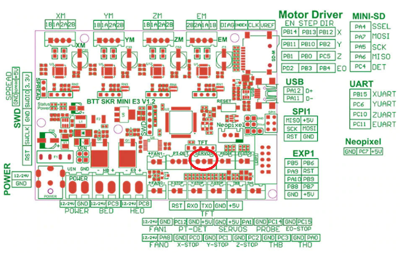
Marlin / src / pins / stm32 / pins_BTT_SKR_MINI_E3.h
#define SERVO0_PIN PC14
#define Z_MIN_PROBE_PIN PA1
#define Z_STOP_PIN PA1
Testing - first steps
- We go up with the Z axis and test if the probe flashes a diode when a metal is applied to its lower part. This determines that it works and that it has power.
- In the printer menu, select Auto Home and add the same piece of metal to the probe during the trip down. The movement of the Z axis should stop - thus we have verified the functionality of the probe.
- We go down manually to verify that the probe in the home position XY has a steel washer under it (if it is not outside it) and the nozzle is NAD the washer .
- We will give home again, this time with our steel pad - if the printer is tangled, we have largely won.
- If we have a dual Z with two independently controlled motors, we manually adjust them by turning each other so that the X axis copies the plane of the washer as best as possible.
- In the printer menu, select Dual Z Align.
- Well, now let's try automatic calibration of the pad using the G29 command.
- If everything went well, we will try a test printout and use Baby Stepping to find the correct Offset for the Z axis (it must be negative !! ). We will then save this.
Temperature sensor calibration
We know the correct function by seeing one extra temperature in the terminal: T: 28.28 /0.00 B: 83.04 /85.00 P: 31.04 /0.00 @: 0 B @: 127
Then just enter the commands:
G76 - performs calibration. It really takes a lot of time, about 1 hour.
M871 - displays measured values
M500 - save to memory
Tip at the end
It is a good idea to stick a square of tinfoil or tinfoil adhesive tape under the pad in the place where the probe is parked in the home position. Just 1x1cm. In the event that for some reason we shout without a steel pad, this square will ensure the detection of the bed and the printer will not try to bend it by all available means, as it will receive a signal in time that it is at home.